Mensaje de error

  • Deprecated function: The each() function is deprecated. This message will be suppressed on further calls en book_prev() (línea 775 de /home1/montes/public_html/drupal/modules/book/book.module).
  • Notice: Trying to access array offset on value of type int en element_children() (línea 6422 de /home1/montes/public_html/drupal/includes/common.inc).
  • Notice: Trying to access array offset on value of type int en element_children() (línea 6422 de /home1/montes/public_html/drupal/includes/common.inc).
  • Notice: Trying to access array offset on value of type int en element_children() (línea 6422 de /home1/montes/public_html/drupal/includes/common.inc).
  • Deprecated function: implode(): Passing glue string after array is deprecated. Swap the parameters en drupal_get_feeds() (línea 394 de /home1/montes/public_html/drupal/includes/common.inc).

Problema 1 (Bode, error de posicion, compensador de atraso)

Solapas principales
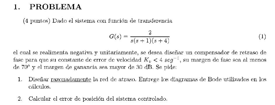
Image 2008Sept1P

SOLUCION:

Apartado 1 (Diseñar razonadamente la red de atraso)


  1. Primeramente vamos a calcular la K dada por el error de velocidad


    \begin{displaymath}K=8\end{displaymath}


    Con lo que el sistema G1(s) nos queda:


    \begin{displaymath}G1(s)=\frac{2 \cdot 8}{s\cdot (s+1)\cdot (s+4)}=\frac{16}{s\cdot (s+1)\cdot (s+4)}=\frac{4}{s\cdot (s+1)\cdot (\frac{s}{4}+1)}\end{displaymath}


  2. Vamos a calcular la nueva frecuencia de cruce wc, sabiendo el margen de fase necesario

    w 0.1   0.4   1   4   10   40
    $\frac{1}{s}$ -90 (0) -90 (0) -90 (0) -90 (0) -90 (0) -90

    $\frac{1}{(s+1)}$

    0 (-45)   (-45) -45 (-45)   (-45) -90 (0) -90

    $(\frac{1}{(\frac{s}{4}+1)}$

    0 (0) 0 (-45)   (-45) -45 (-45)   (-45) -90
      -90 (-45) -117 (-90) -152.81 (-90)   (-90)   (-45) -270

    El valor de wc viene dado por la frecuencia que tiene el siguiente angulo de fase:


    \begin{displaymath}-180+margenfasedeseada+12=-98\end{displaymath}


    \begin{displaymath}\lfloor{G1(j0.4)}=-90-45\cdot log(\frac{0.4}{0.1})=-117\end{displaymath}


    \begin{displaymath}\lfloor{G1(j1)}=-117-90\cdot log(\frac{1}{0.4})=-152.81\end{displaymath}


    \begin{displaymath}\lfloor{G1(j1)}=-117-90\cdot log(\frac{4}{0.4})=-207 \end{displaymath}


    \begin{displaymath}\lfloor{G1(jwc)}=-90-45\cdot log(\frac{wc}{0.1})=-98\end{displaymath}


    \begin{displaymath}\frac{wc}{0.1}=10^{\frac{-98+90}{-45}};wc=0.1\cdot 10^{\frac{-98+90}{-45}}=0.15\end{displaymath}


    Esta sera la nueva frecuencia de corte


  3. Vamos a escoger $\frac{1}{T}$ tal que


    \begin{displaymath}\frac{1}{T}=\frac{wc}{10}=0.015\end{displaymath}

4. Vamos a calcular $\beta$


\begin{displaymath}-G1(jwc)=-20\cdot log(\beta)\end{displaymath}


\begin{displaymath}20\cdot log(4)=12.04\end{displaymath}


w   1   4  
$\frac{1}{s}$ (-20)   (-20)   (-20)

$\frac{1}{(s+1)}$

(0)   (-20)   (-20)

$\frac{1}{(\frac{s}{4}+1)}$

(0)   (0)   (-20)
  (-20) 12.04 (-40) -12.04 (-60)

\begin{displaymath}G(j4)=12.04-40\cdot log(4)=-12.04\end{displaymath}


\begin{displaymath}G1(j0.15)=12.04-20\cdot log(0.15)=28.52db\end{displaymath}


\begin{displaymath}-20\cdot log(\beta)=-28.52\end{displaymath}


\begin{displaymath}\beta=26.67\end{displaymath}


Con lo que ya tenemos casi el compensador:

\begin{displaymath}G_{c}(s)=K_{c}\cdot \frac{(s+0.015)}{s+\frac{0.015}{\beta}}=K_{c}\cdot \frac{(s+0.015)}{(s+0.0005)}\end{displaymath}


5. Ahora vamos a calcular la $K_{c}$

\begin{displaymath}K_{c}\cdot \beta =K\end{displaymath}


\begin{displaymath}K_{c}=\frac{K}{\beta}=\frac{8}{26.67}=0.3\end{displaymath}


Con lo que el compensador nos queda:

\begin{displaymath}G_{c}(s)=0.3\cdot \frac{(s+0.015)}{(s+0.0005)}\end{displaymath}


La fase en wc del sistema es:

\begin{displaymath}\lfloor{G_{jwc}(s)\cdot G(jwc)}=-100\end{displaymath}


Con lo que el margen de fase como vemos a continuacion verifica las condiciones

\begin{displaymath}margenfase=180-100=80>70\end{displaymath}


Vamos a calcular el margen de ganancia
w 5E-5   5E-4   1.5E-3   5E-3   1.5E-2   1.5E-1

$\frac{1}{(\frac{s}{0.0005}+1)}$

0 (-45) -45 (-45)   (-45) -90 (0) -90 (0) -90

$(\frac{s}{0.015}+1)$

0 (0) 0 (0) 0 (45)   (45) 45 (45) 90
G1(s) 0 (-45) -45 (-45)   (0)   (45) -45 (45) 0
  -90 (0) -90 (0) -90 (0) -90 (0) -90 ()  


\begin{displaymath}\lfloor{G1(jwcf)}=-117-90\cdot log(\frac{wcf}{0.4})=-180 \end{displaymath}


\begin{displaymath}wcf=5\end{displaymath}


\begin{displaymath}G_{c}(j5)\cdot G(j5)=-48dB<-30dB\end{displaymath}


Verifica las condiciones de margen de ganancia


Apartado 2 (Vamos a calcular el error de posicion del sistema controlado)

\begin{displaymath}G_{c}(s)\cdot G(s)=0.3\cdot \frac{(s+0.015)}{(s+0.0005)}\cdot \frac{2}{s\cdot (s+1)\cdot (s+4)}\end{displaymath}


Como el sistema es de tipo I. El error de posicion va a ser cero.


\begin{displaymath}e_{p}=\frac{1}{\infty}=0\end{displaymath}


Vamos a hacer los calculos y las comprobaciones de resultados con el Scilab


clear;
s=%s;
g=2/(s*(s+1)*(s+4));
gs=syslin('c',g);
aux=horner(s*gs,0)
kv=4;
k=kv/aux
g1=k*gs
fwc=-180+70+12
wc=0.1*10^((fwc+90)/(-45))
aux2=horner(g1,%i*wc)
aux3=atan(imag(aux2),real(aux2));
aux4=360*aux3/(2*%pi)
a=wc/10;
aux5=20*log10(abs(aux2))
g1015=20*log10(4)-20*log10(0.15)
g04=20*log10(4)-40*log10(4)
bet=10^(g1015/20)
b=a/bet
kc=k/bet
gc=kc*(s+a)/(s+b)
gt=g*gc;
gts=syslin('c',gt);
aux6=horner(gts,%i*5)
aux7=20*log10(abs(aux6))
s1=s/(2*%pi)
gb=2/((s1+0.000000001)*(s1+1)*(s1+4));
gcb=kc*(s1+a)/(s1+b);
gtb=gb*gcb;
gbs=syslin('c',gb);
gcbs=syslin('c',gcb)
gtbs=syslin('c',gtb)
[mg,frg]=g_margin(gtbs)
[mp,frp]=p_margin(gtbs)
clf;
bode([gbs;gcbs;gtbs],['compensado';'compensador';'no compensado'])
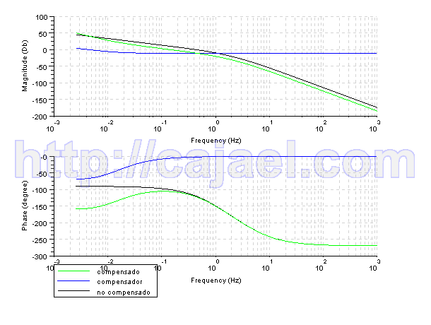
Image P1sept2008ps


Español

Añadir nuevo comentario

Plain text

  • No se permiten etiquetas HTML.
  • Las direcciones de las páginas web y las de correo se convierten en enlaces automáticamente.
  • Saltos automáticos de líneas y de párrafos.
Pin It